17/09/15. One Year on!

Yesterday was exactly one year since this engine came into my possession and I started this project. Now if I was organised and had gone at it hammer and tongs, I would probably have a running engine by now, gleaming and chugging away in the autumn sun.

But I haven’t 😦

However, I’m not in any race to finish it and I know I will get there, eventually!

Today I have removed the splash guard from the sump and then the sump plug in order to drain a mixture of water, sludge and old oil from the sump. In addition to this I have removed the oil filler, which itself was full of horrible black sludge. These parts have been given a good clean in paraffin to remove all the old oily deposits. The sump guard and the oil filler wing nut have been given a quick spray with high temperature exhaust paint and the oil filler and cover have been wire brushed and then given a coat of red oxide.

IMG_3774 (Medium)

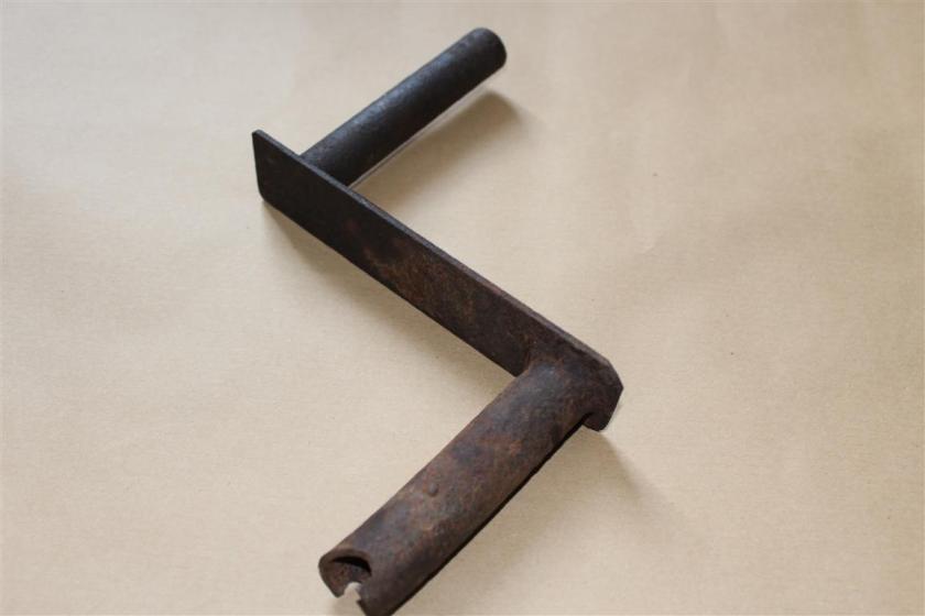
The parts as removed from the engine


IMG_3776 (Medium)

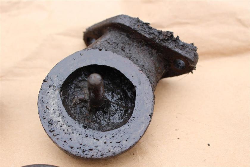
Oil filler, full of sludge


IMG_3782 (Medium)

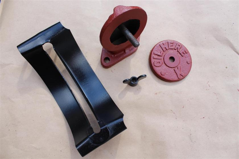
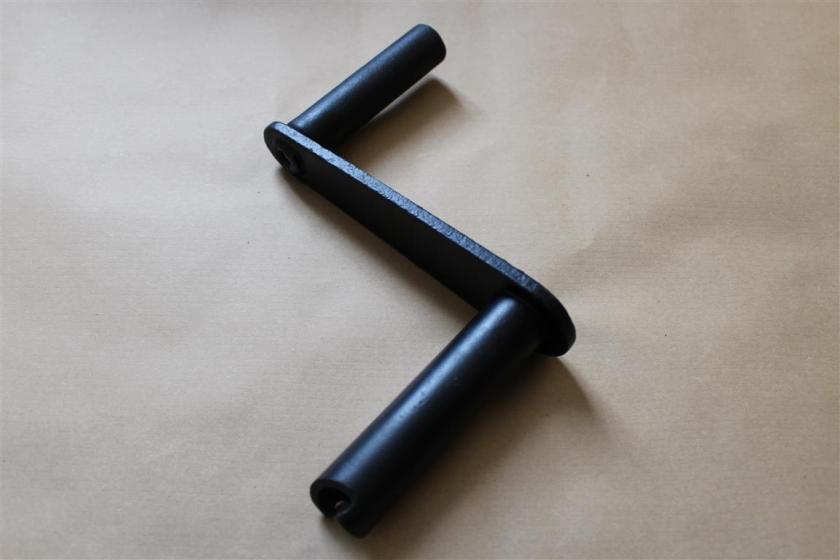
The same parts, cleaned, rubbed down and painted


This now means that all external parts have been removed from the engine. Those that were unserviceable or incomplete have been replaced and those that were ok have been cleaned up and given a coat of red oxide (where appropriate). I still have to sort out the carburettor, but I have the parts I need in order to do this. The fuel tank needs rubbing down and some small dents in it need filling before it can be painted. I also need to sort out the magneto, which now looks great but doesn’t spark. This is something that I will worry about as the restoration nears completion.

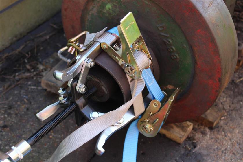
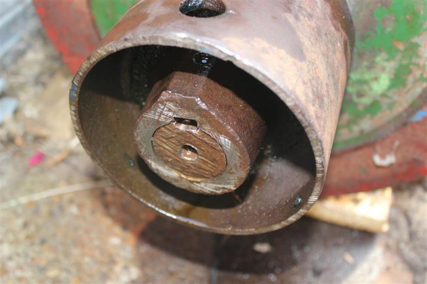
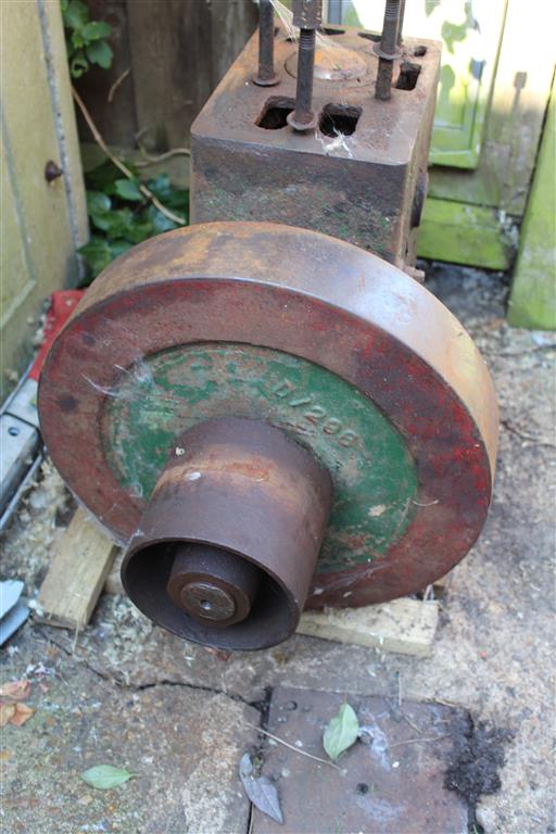
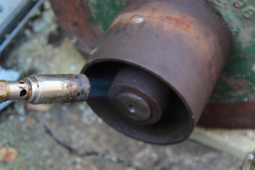
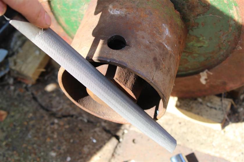
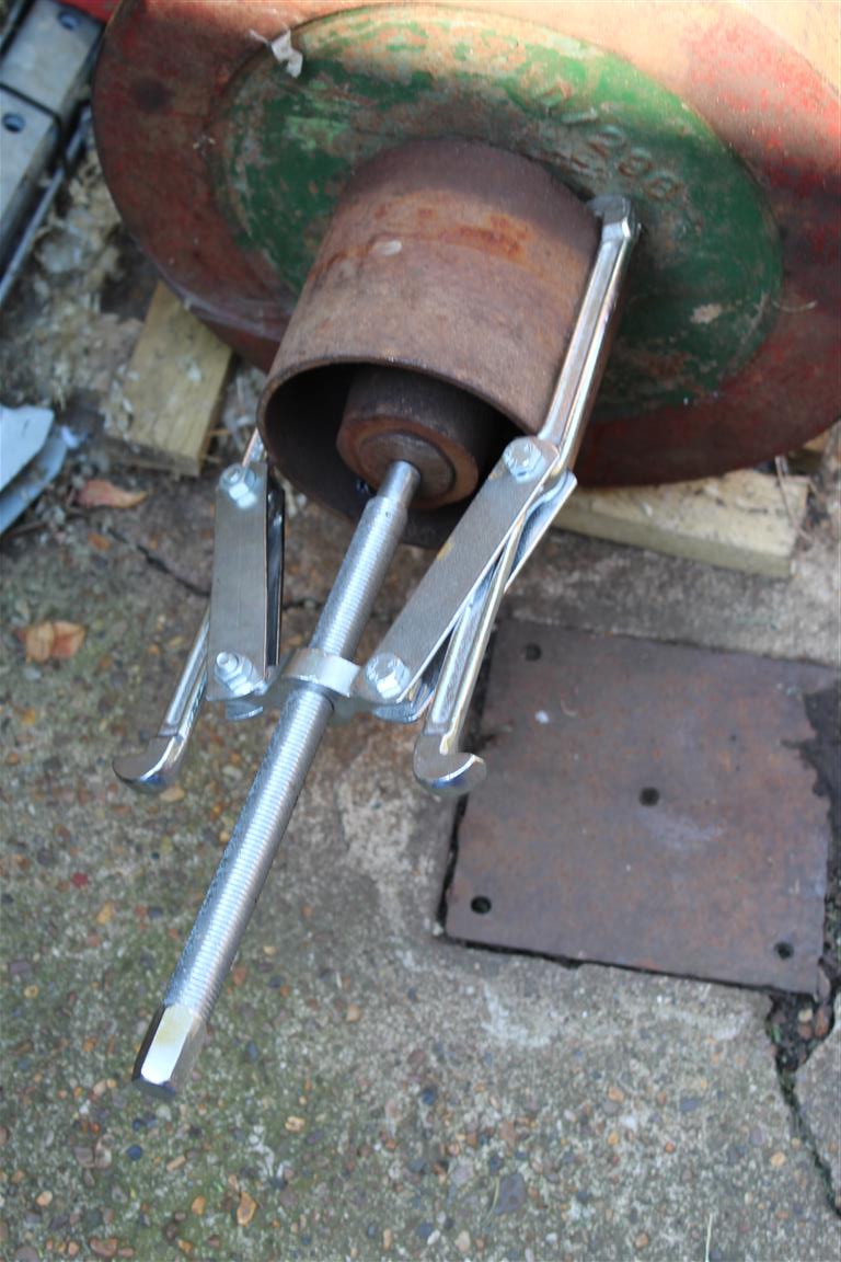
The next task is to address the pulley and flywheel which are still attached to the crankshaft. If I don’t have any joy soon, I am going to remove the nuts from behind the flywheel and extract the crankshaft, flywheel and pulley as one complete piece and worry about that later. This will allow me to finally get to cleaning up the engine block and painting it. Then it can be mounted on the trolley and the process of building it back up piece by piece can begin.

31/07/15. Pulley Progress II

Ok, so the pulley is very reluctant to come off. Desperate times call for desperate measures. Out came the angle grinder to remove about an inch off the back of the pulley.

IMG_2528 (Medium)

The first cut


IMG_2529 (Medium)

Back end of the pulley cut away


The two legged puller had proved unsuccessful in getting the pulley to move. This was mainly due to the fact that it would shift and twist when a load was applied and therefore would not pull straight. I have decided that a three legged puller may centralise the load and apply a direct force in line with the crankshaft, which might get the damned thing to budge. The three legged puller however, did not have sufficient reach and so the pulley needed cutting.

I shall leave it under tension and keep applying the oil to see if it will eventually move. The last resort is to try and cut the pulley off, but I don’t really fancy this option.

IMG_2530 (Medium)

Three legged puller, strapped down, under tension

21/07/15. Pulley Progress

Tonight after work I decided to have a go at that pulley again. I really want to shift the pulley and flywheel and get this restoration moving.

Last time I’d managed to hit the pulley further onto the crankshaft which kind of defeated the object of getting it off. It did however allow me to clean up the end of the crankshaft which itself was a bit battered. Tonight I used a huge car tyre lever and a crowbar to apply some force to the back of the pulley. It has moved forward about a 1/4″ and now the end of the crank is more or less flush with the end of the pulley. I’ve applied loads of penetrating oil and now I’ll leave it for a while to let it soak in. Hopefully now that it has moved in both directions, I’ll be able to “persuade” it to give up the fight and just come off. Fingers crossed!

IMG_2524 (Medium)

Movement at last!

19/07/15. Weeting Steam Rally


Ok, so this is not strictly about my restoration, but like all vintage machinery enthusiasts, I like to go to shows and rallies from time to time (although I’m just a spectator!)

Weeting Steam Rally & Country Fair at Fengate Farm, Weeting, Norfolk, is a fantastic show that offers something for everyone.

Like all good shows of this type, there’s always an excellent line up of stationary engines and there, of course, were a selection of Lister D-types to see. I snapped a few pictures of these for some inspiration and have posted them below.

Hopefully one day I too will be amongst the exhibitors with my old engine chugging away! Got to get it running first though.

Anyway, if you’re interested in a good show in Norfolk then you should look no further than Weeting. It is usually held around the 3rd weekend in July. Go to www.weetingrally.co.uk for more information.IMG_2247 (Medium)IMG_2252 (Medium)IMG_2253 (Medium)IMG_2245 (Medium)

11/07/15. Flaming Flywheel

As ever this restoration seems to go at one pace, dead slow! Today I thought I’d have another go at trying to get the pulley and ultimately the flywheel off the crankshaft.

IMG_2123 (Medium)

The pulley and flywheel


I thought that the application of some heat, may assist in trying to get the pulley to move. I’ve heated it, whacked it with a persuader and applied the puller again in the hope of getting it off.

IMG_2126 (Medium)

Applying some heat


I think the heat must have done something as although it has not moved outwards, it has moved in towards the flywheel when given a few taps with a large hammer.

Now I know that driving the pulley further onto the crankshaft is not the aim of this exercise, but it does prove that it will move and it has enabled me to file round the end of the crankshaft. The end of the shaft was quite bashed up and there was a raised edge which would prevent the pulley coming off if it was free.

IMG_2135 (Medium)

Removing burrs from the end of the crankshaft


I’m going to try some more heat and possibly apply some force from behind the pulley to see if it will budge. The pulley itself is cracked and not in very good shape, so wrecking it in its removal is not a problem.

IMG_2133 (Medium)

The puller vs. the pulley!


A last resort will be to undo the nuts behind the flywheel to extract the crankshaft, flywheel and pulley in one piece. If I do this, then I will probably seek help in trying to separate the pulley and flywheel from the shaft, possibly from someone with a hydraulic press.

I really need to get the engine block completely stripped so I can get on with cleaning it up and getting it painted. Then it can be mounted on the trolley and the process of putting the engine back together can begin.

09/07/15. Thanks Patrick!

IMG_2141 (Medium)

Some time ago I thought I’d e-mail the Editor of Stationary Engine Magazine, Patrick Knight, cheekily asking if he’d give my blog a mention on the letters page.

Well I’m extremely pleased and grateful to say that he has obliged! I’ve been a subscriber to SE for over 10 years now, but this is the first time that I have written in and now I’ve made the letters page!

Thanks Patrick! 🙂

20/05/2015. Getting the right mixture?

Its been a while since I’ve done anything engine related. Being a back yard restoration means I’m heavily reliant on good weather, and although we’re well into May, there’s still quite a lot of rain around!

There are however, plenty of small jobs that I can still undertake indoors, even if it does upset the wife. The dining room table I’m informed, is not a substitute work bench!!

I thought I’d make a start on the carburettor. The carb that came with the engine, was missing its float chamber. Thankfully I managed to snap up a spare carb with its float chamber from good old eBay!

IMG_1506 (Medium)

The original carb, as removed from the engine


I hope to be able to use the original carburettor by adding the float chamber from the spare. In the mean time I’ll try and strip down, clean up and prime the carb so that it’s ready for its top coat of paint before reassembly. More pictures and updates to follow….

IMG_1505 (Medium)

The donor carburettor with the float chamber I require

25/04/15. The Stationary Engine Magazine Log Sheet.

Stationary Engine magazine have been kind enough to supply in their May 2015 issue, an engine exhibit log sheet, which gives owners of stationary engines a chance to list and describe their pride and joy. I have taken the opportunity to fill in the details for my engine ( albeit a little early ) in the hope that one day, I may be able to show my engine to fellow enthusiasts and the wider public!

IMG_1485 (Medium)

My exhibit log sheet

25/04/15. Can you handle it?

So having decided that the starting handle supplied with the engine was not really up to the job, a suitable replacement was sought.

Thankfully, good old eBay came up with the goods. I was able to source a more or less new starting handle for £14.00 including delivery.

Although it doesn’t show up in the photos, there are one or two small holes in the old handle due to rust. It possibly looks like this was a home made or cheap handle as it is made from much thinner stock.

The new handle is much more robust than the old one, it seems to be a modern remanufactured version, made from a heavier gauge of steel. These handles retail at £25.20 plus postage, so to get one for £14.00 all in is more or less half price!!

IMG_1482 (Medium)

The old rusted starting handle…..


IMG_1484 (Medium)

…..and the new much more robust one!

16/04/15. The Governor reassembled

In addition to the work on the trolley, I was able to reassemble the governor, now that I had received the new springs. The worn pins in the governor weights have been refitted upside down, so that a clean domed head is uppermost. This will hopefully help with the overall running and idle speed of the engine.

IMG_1470 (Medium)

New springs fitted to the governor….


A useful site for the sourcing of spares for stationary engines, in particular the Lister d-type is: http://www.stationaryengineparts.com/

IMG_1474 (Medium)

……and refitted to the housing