04/10/15. Trolley Trouble II

Many months ago I had acquired a wooden trolley frame that I had varnished and fitted the axle and wheels to. This was stored away awaiting the restoration to reach a stage where I could mount the crankcase on the trolley. As I had more or less reached that point, I got the trolley frame out only to find that the timbers had warped and it would be no good for the job! 😦

So rather than go to the expense of buying another frame, I thought I’d have a go at making one myself. I got an 8′ length of 3″ x 2″ from the local hardware store and set about making a basic frame.

IMG_3854 (Medium)

IMG_3855 (Medium)
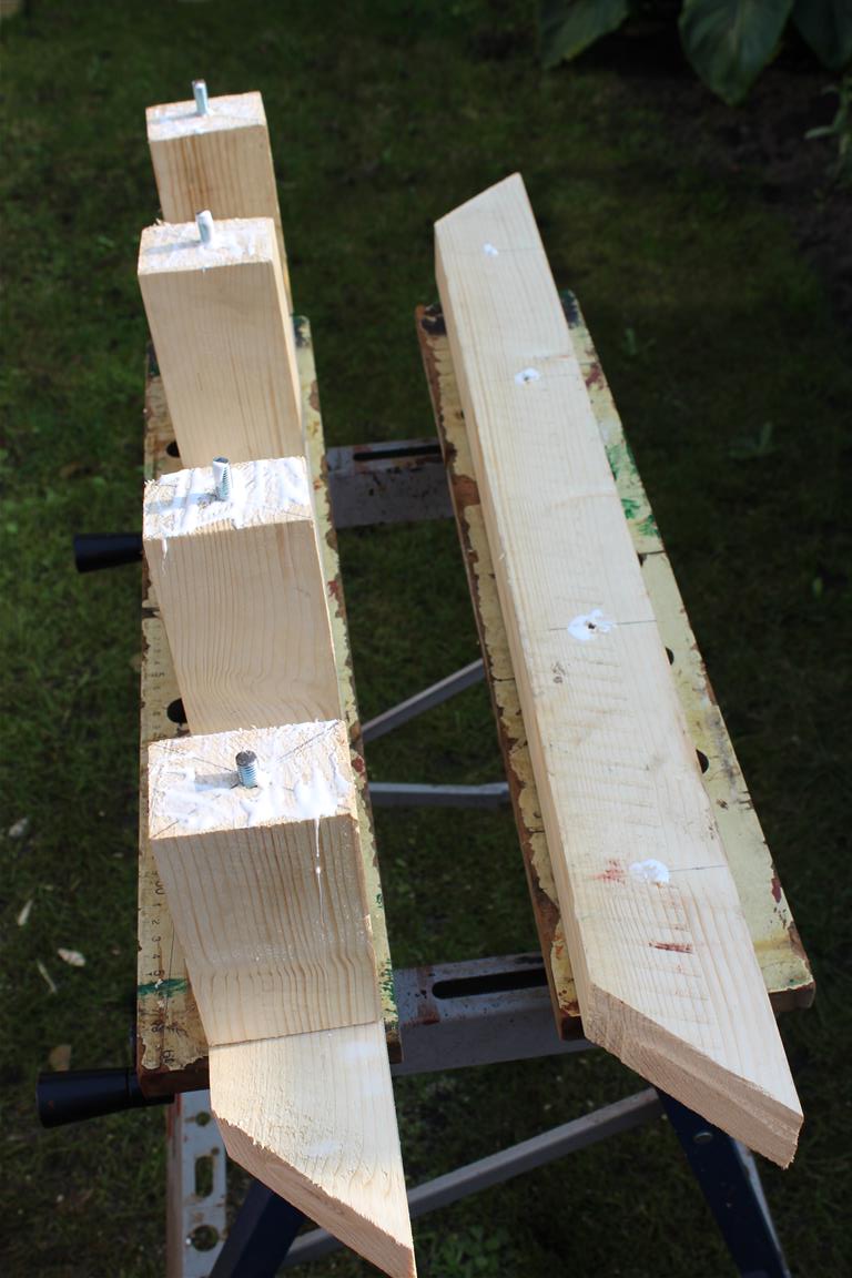
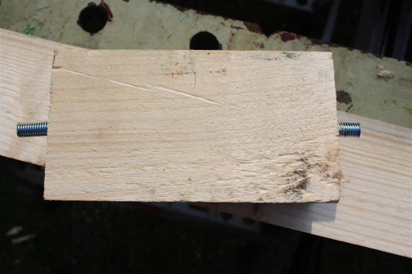
I cut two identical outer pieces and then joined these together with four smaller pieces of wood. I used some threaded bar as dowels to hold it all together, as you can see above.

IMG_3856 (Medium) IMG_3857 (Medium)

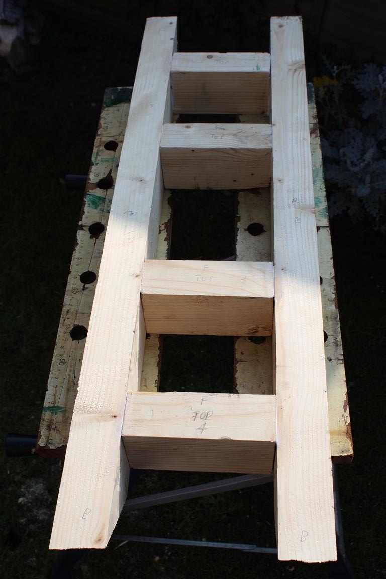
Once assembled it doesn’t look too bad. As I pointed out yesterday, I’m not a painter and neither am I a carpenter! It has one or two gaps, scrapes, knots etc, but I’m quite pleased with it.

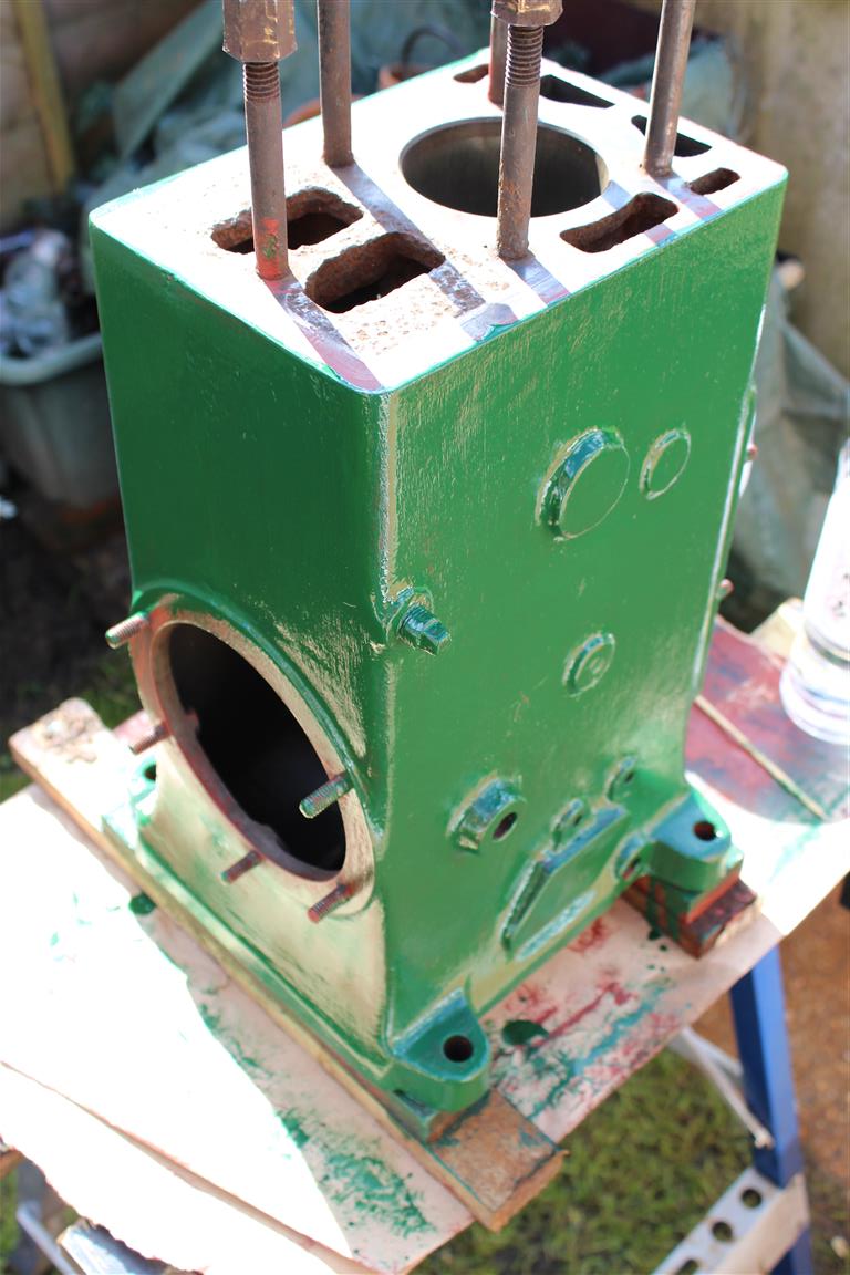
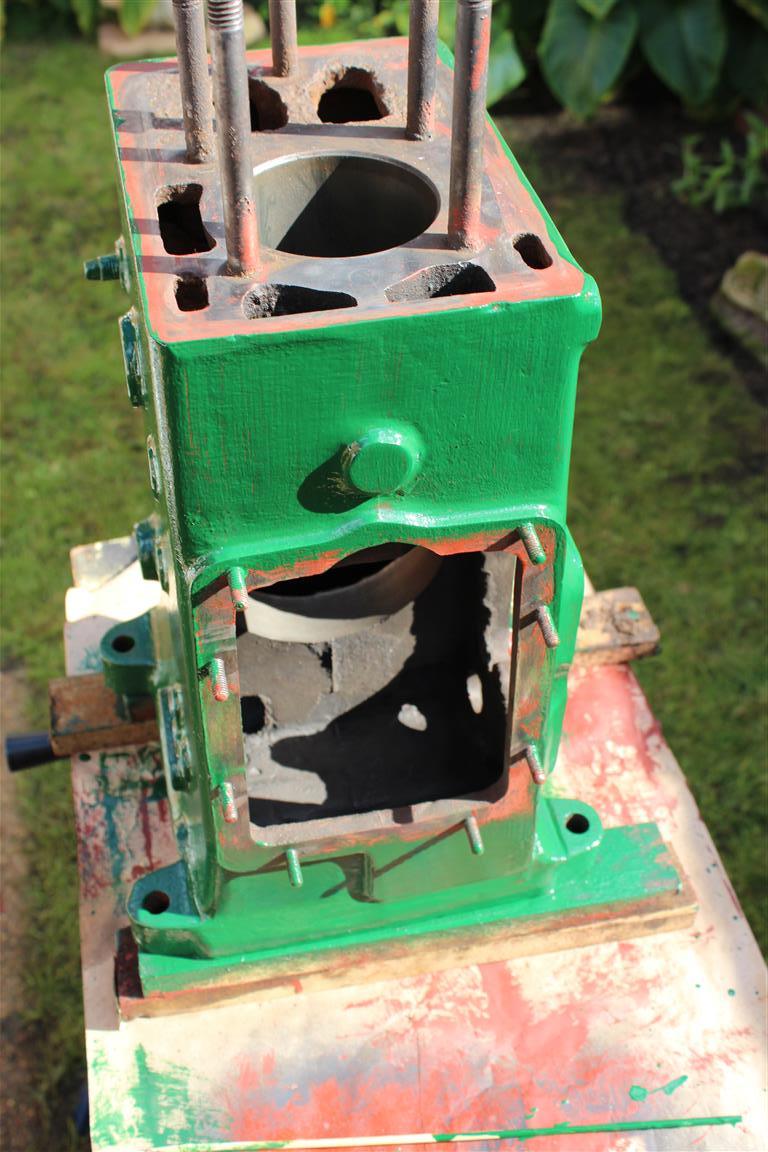
I decided that it would be a good idea to fit the wheels and the handles as well, just to see how it all worked, and to work out the location for mounting the crankcase.

IMG_3867 (Medium)IMG_3866 (Medium)

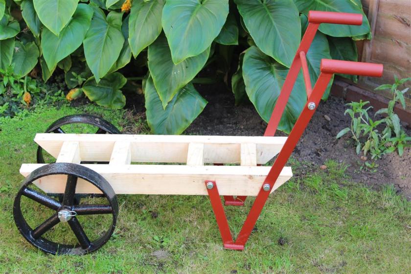
I now need to dismantle the trolley again in order to rub down, stain and varnish the wood, paint the handles and give the wheels another coat of paint. The pictures above give you an idea of how it will eventually look. Once the trolley is finished, I can mount the crankcase and start to refit the other components and cylinder head. I know it’s October now, but could there be a possibility of a Christmas day crank up?

Now that would be good!

03/10/15. Tap Tastic

I had to acquire a 3/8 BSP tap to tidy up some of the threads that are cut into the crankcase. These are the water drain tap hole, both oil sump drain plug holes and the mounting hole for the post that supports the governor mechanism.

IMG_3850 (Medium)

The 3/8 BSP Tap


With years of paint, rust and grease in these holes, not to mention what I had added (with paint etc), they needed cleaning out. Unfortunately I didn’t possess a suitable holder for the tap, but as you can see from the photos, a pair of molegrips were an equivalent substitute. All these threads were cleared out, ready for their intended component, which will hopefully be a snug fit!

IMG_3851 (Medium)

Tapping out the water drain tap hole


03/10/15. Painting Progress II

The crankcase today received its third coat of engine enamel. I think I’ll stop at three. In between coats it was rubbed down with 600 grit wet and dry paper. At least now it has a decent barrier to protect it from the elements.

IMG_3845 (Medium) IMG_3846 (Medium)

I also have given the other smaller components (fuel tank, covers etc) two coats of Mid Brunswick Green. Admittedly it’s not the best paint job in the world, but then I’m not the greatest painter. It definitely helped by thinning the paint slightly, as enamel paint is quite thick and therefore prone to drips and sags. Working with this kind of engine or coach enamel involves applying the paint to an area fairly thickly, but then “laying” it off with the brush to draw it out and ensure an even application. This is all part of the learning experience of doing this engine restoration. You have to be prepared to turn your hand to many different tasks!

27/09/15. Painting Progress

With the primer on the crankcase dry, I applied the first coat of Mid Brunswick Green. I mixed up a solution of 90% paint with around 10% thinners to try and make it easier to apply. Engine enamel paint is quite thick, so using thinners made it a little easier to brush on.

It hasn’t gone on too badly, but despite using a brand new Harris brush, there are still one or two bristles stuck in the paint as well as the usual airborne fluff, dust and insects that will no doubt attach themselves to it as it dries. I will rub it down again lightly with 600 grit wet & dry before the second coat.

IMG_3837 (Medium)IMG_3838 (Medium) IMG_3839 (Medium)

I know that most people would probably paint the engine as one complete job, with all the other components attached. However, I need to paint the crankcase separately so that I can then fit it to the trolley, ready to fit all the other parts. I still need to be able to lift the engine at this stage, and minus the flywheel and crankshaft it is relatively easy to move around and lift onto the workbench.

I also looked at the crankshaft today, with a view to removing the shaft from the bearing housing. I removed the four bolts securing the plate at the flywheel end of the crankshaft to expose the oil thrower. This is held on by a circular clip and a grub screw. I removed these but could not get the oil thrower to move. It was at this stage that I decided that perhaps I would leave this assembly alone, as it doesn’t really need any attention. It is so heavily over specified that I’m sure it will be ok.

IMG_3836 (Medium) IMG_3833 (Medium)

I packed the front (flywheel end) bearing with loads of grease before refitting the cover. I then applied a coat of primer to the exposed parts.

IMG_3840 (Medium)

Once the crankcase is fitted to the trolley, I will replace the crankshaft, piston and governor housing before fitting the cylinder head. That will probably be my next main task. Grinding the valves and fitting them back with the new springs that I have purchased.

26/09/15. Crankcase Cleaning II

So it was on with cleaning up the crankcase ready for painting. First of all I used a wire brush attachment in a cordless drill to remove the worst of the rust and old paint.

IMG_3822 (Medium)

Attacking the rust!


Then I switched to an 80 grit flap disc fitted to the angle grinder. This was good at removing small casting marks that have obviously been there since the engine left the factory in 1942!

IMG_3829 (Medium)

Rubbed down….


IMG_3828 (Medium)

….and ready for paint!


One other problem that I’d left since very early on in the restoration was the sheared off water drain tap. There was a horrible looking old tap, almost like a bathroom tap, on the engine when it was purchased. I’d managed to shear this off flush with the crankcase when attempting to remove it.

Using a cold chisel and a hammer, I managed to cut through the softer brass tap thread and peel it away from the casting and extract it. This will allow me to now fit a smaller more suitable drain tap.

IMG_3826 (Medium)

Peeling away the old material ready for the new tap


IMG_3827 (Medium)

Internal thread cleared ready for the new tap

With that completed, at last a coat of red oxide could be applied to the crankcase. I aim to apply two coats of red oxide followed by two coats of the Mid Brunswick Green engine enamel. This will be four coats of paint in total over the bare metal, which I think will give a good barrier against the elements. This will hopefully preserve this engine for many more years to come.


IMG_3832 (Medium)

The first coat of red oxide primer

IMG_3831 (Medium)


21/09/15. Crankcase Cleaning

What a weekend it has been. I have made a massive amount of progress with the restoration and the hardest parts are out of the way.

IMG_3806 (Medium)

The flywheel is off!


IMG_3809 (Medium)

Note the piece of wood wedged against the crankshaft web. This allowed me to twist and pull the flywheel off the shaft without it rotating.


Most significantly, the flywheel is at last off the crankshaft. With the gib key removed, it was rotating freely about the crankshaft, but I wedged a piece of wood against the crank web through the crankcase door. This allowed me to spin and move the flywheel up the shaft and liberate it from the engine.

This then allowed me to remove the 5 nuts holding the bearing housing to the crankcase and extract the crankshaft and bearing housing as one piece.

I could then slide the piston up the bore and extract it from the top. The piston and rings look in really good shape. I was considering replacing the piston rings, but as everything looks so good, I think I’ll save myself the £47. It does make me wonder if this engine has previously been restored or at least had an overhaul at some point in its life.

IMG_3813 (Medium)

The crankshaft bearing housing


IMG_3812 (Medium)

The piston & connecting rod


With an empty crankcase, I could get on with cleaning all the old oil and rust out. I washed out the innards of the engine with paraffin and an old toothbrush and a paintbrush.

IMG_3814 (Medium)

The insides of the crankcase cleaned…..


IMG_3818 (Medium)

….and from the other side


The next task was to clean out the accumulation of rust in the water jacket. With the engine stripped of all its components, it was now an easy job to turn it upside down and let gravity help with this job! I also used a large flat screwdriver to scrape away at the sides of the water jacket, to remove yet more flaky pieces of rust

IMG_3819 (Medium)

IMG_3820 (Medium)


Altogether I recovered around 2lbs of loose rust from the engine! The next job will be to clean up the crankcase with a rotary wire brush fitted to a drill and a sanding pad fitted to the grinder. Then it can have a coat of red oxide primer and two coats of mid Brunswick green. All that however, can wait until next weekend. I’m off for a well earned rest!

20/09/15. Fuel Filler II

Whoa! Three posts in one day! More has happened today than I ever dreamed possible. What with all the excellent progress with the pulley and flywheel removal, I have also made good progress with the fuel tank. Having filled the dents and rubbed the tank down again, I was able to give it a coat of red oxide primer and tick another item off the list of things to do. I am expecting a delivery this week of a litre of Mid Brunswick Green paint, sourced from Craftmaster Paints, who are based in Over in Cambridgeshire, UK. They have a good reputation for supplying high quality engine enamel and other paints for the heritage restoration market.

You can find out more of what they offer by going to: http://www.craftmasterpaints.co.ukIMG_3804 (Medium)IMG_3803 (Medium)

20/09/15. Grinder Gripes

Just a little aside from the restoration, but I’d thought I’d share my thoughts on angle grinders. I had purchased a cheap 4.5″ or 115mm grinder for £20, but unsurprisingly it developed problems after only a few uses. The first being the nut or grinding disc retaining flange that holds the grinding disc in place. It decided to seize solid, and refused to come off. I bent two removal tools trying to get it off. Secondly the spindle lock mechanism broke in my attempts to get the outer flange nut off.

IMG_3802 (Medium)

Bosch GWS 7-115 240 Volt Grinder


So realising the error of my ways and hearing the “buy cheap, buy twice” mantra ringing in my ears, I spent a little bit more on a Bosch angle grinder which I have to say I’m very pleased with. In addition to that I also purchased a Bosch SDS “clic” quick release retaining flange nut, which is effectively a tool free way of holding the grinding disc onto the grinder. It’s easy to put on and remove just by screwing or unscrewing by hand. No more problems with the nut getting stuck or messing about with flimsy removal tools which end up getting bent out of shape!

IMG_3795 (Medium)

Bosch SDS-clic quick release nut

20/09/15. Pulley Progress III

Well. Where do I start? I’ve achieved more in an hour today working on the engine than I have all year!

The problematic pulley was still putting up a fight and refusing to come off by conventional means. I’d already resigned myself to cutting the pulley into pieces in order to get it off. Today I cut off the front of the pulley (parallel to the flywheel) in order to make a lateral cut into the pulley in line with the crankshaft. I couldn’t quite cut all the way through, but I was able to cut enough to insert a crowbar and give it a few hefty whacks with a club hammer. This loosened its grip on the crankshaft and with a few more whacks from behind, it was off!

IMG_3790 (Medium)

The pulley with crow bar inserted


IMG_3793 (Medium)

The pulley now removed and in pieces


The next job was the flywheel gib key. Spurred on by the success with the pulley I put to use the flywheel key puller that I had purchased several weeks ago on ebay.

I had to use a flat file to square up and remove some of the back of the gib key in order to slide the puller over the head of the key. To my amazement a few turns on the bolts and the key started to slide out very easily!

IMG_3797 (Medium)

The puller in action


I have read before about D-types that have a pulley fitted, being easier to extract the flywheel key from, as the pulley provides a little protection from the elements. Either way, it was very easy. You hear horror stories of key heads snapping off or being rusted solid in the keyway and all sorts of difficult and time consuming solutions to get them out. For once luck is on my side. As if all that wasn’t enough, the flywheel now rotates freely around the crankshaft, so I hope to be able just to twist and slide it straight off. Fingers crossed!

IMG_3798 (Medium)

The flywheel gib key


IMG_3800 (Medium)

Keyless at last!


18/09/15. Fuel Filler

IMG_3784 (Medium)

The fuel tank before, complete with numerous dents!


So the fuel tank, although complete and free of holes, had several dents in it that needed attention. I rubbed down the tank which had already been painted by the previous owner, in order to fill the dents. I used an ordinary filler for automotive use, called Isopon P.38

IMG_3786 (Medium)

The tank rubbed down…..


IMG_3787 (Medium)

….and filled.