19/08/17. Sparking into life!

IMG_6561 (Medium)

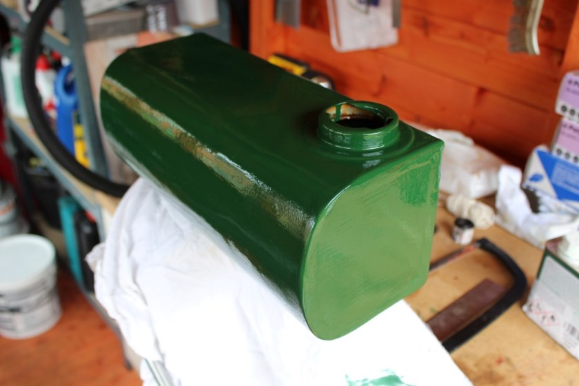
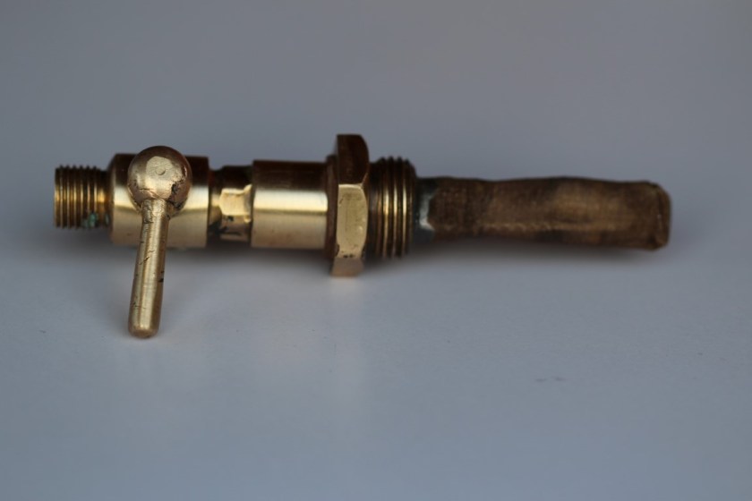
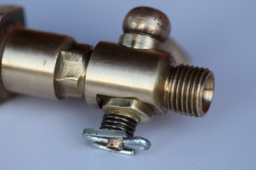
So nearly a full four years after buying the engine and probably three and a bit years spent working on it, she is running at last! There are still one or two jobs left to do, and there are some teething troubles, but nothing major. The fuel tap on the bottom of the petrol tank appears to leak. It’s not the threaded parts into the fuel tank or fuel pipe, but it seems to leak from the actual fuel tap itself. I’m not sure what to do about that, other than to buy a new tap. 

Consequently, getting her to run involves pouring some fuel directly into the float chamber, because I cannot chance fuel leaking out directly adjacent to a hot exhaust! This means she will only run for a few minutes, until the fuel in the float chamber has all gone. I will have to replace the fuel tap in order to fill the fuel tank and then I can run the D-type for an hour or so to see how she performs.

As for the magneto, the guy that was going to rewind the coil hadn’t even started it, despite having had it for three months! I decided to cut my losses and got him to send it back. I kept an eye on ebay for a couple of weeks and luckily I managed to get a working Lucas RS1 magneto for just over £50. This is what I have fitted in order to get her running. Sadly I missed the 75th anniversary by one day, but she ran again 75 years and one day after she was first delivered to her new owner on the 18th August 1942!

06/08/17. A very nearly finished engine!

Since my last post, I have fitted the petrol tank, the fuel tap and the pipe to the carburettor as well as fitting the magneto chain cover

IMG_6561 (Medium)

I am of course still waiting on the magneto, so as yet, there is no life in the engine.  There are still a few small cosmetic jobs to do, but I’m more or less ready to run. I hope that day will be soon!

IMG_6564 (Medium)

The fuel tap and pipe


IMG_6565 (Medium)

The magneto chain cover


IMG_6562 (Medium)

The carburettor and exhaust


IMG_6567 (Medium)

The all important Lister logo


IMG_6566 (Medium)

The (almost) finished restoration

As soon as she is running, I will make a video and post it on YouTube. I’ll put a link in from this blog, so you can have a look.


29/07/17. If the cap fits and tanks a lot.


I’m not sure if I’d already mentioned that the fuel filler cap for my Lister D was a jam jar lid. Yes, that’s right a jam jar lid! The tank has a wider automotive style (be it car or motorbike?) filler spout and one that fits a bayonet style cap. 

IMG_6550 (Medium)

IMG_6551 (Medium)

The home made fuel cap!


Presumably the original cap had been lost, because the jam jar lid (I’m assuming here it’s jam, it could be marmalade or pickled onions for all I know!), has had a thin strip of steel tack welded inside to secure it to the tank opening.

The D-types I’ve seen from a similar vintage have a screw on brass cap and fitting, which is smaller than the opening in my tank. Obviously this must be some kind of back yard repair job. Having said that, the tank (apart from the dents) is in very good condition and doesn’t look like a 75 year old fuel tank. I suspect it is a remanufactured part that has had a car style filler spout and cap fitted in the absence of an original.

Hence I hunted around for a spare, looking for something for a car or motorbike that would fit the wider opening and have a bayonet fitting. Yet again, good old ebay comes up trumps with a replica brass filler cap being sold as a replacement part for a Royal Enfield motorcycle. It came all the way from India (where motorcycles are still made under the Royal Enfield name), for £10 including postage.

It needs a bit of a polish up, but it will look a lot neater than a flimsy old jam jar lid! Having previously carried out some more filling of a dent in the fuel tank and given it another rub down and clean, it was time to apply some more of the good old Mid-Brunswick green paint. 

IMG_6548 (Medium)

The freshly painted fuel tank

Once the tank and the tank straps are dry, I can fit them to the engine and connect the fuel pipe from the tank to the carburettor. Once that’s done, I’m just then waiting on the magneto, before I can have a go at firing the engine up! The end is in sight, but there are still a few bits and pieces to do. 

It has taken me nearly three years to get to this point!

16/07/17. Weeting Steam Rally

On the weekend of 14th, 15th & 16th of July 2017 was the annual Weeting Steam Rally in Suffolk. This is a relatively local show to me and has grown over the years to be quite a significant event on the calendar of any vintage enthusiast. There is always a superb collection of Steam Traction engines, Tractors, Vintage cars and Trucks and of course Stationary Engines!

I took the opportunity to photograph as many as I could. Naturally I was particularly interested in the Lister D-types on show, but there were a lot of other fine looking engines that also drew my attention.

There was an interesting D-type powered cement mixer, that was running on the day. 

IMG_6546 (Medium)IMG_6547 (Medium)

As well as a few other examples…..

09/07/17. Fuel Tap

The fuel tap that fits to the opening in the base of the fuel tank was quite dirty and the tap itself was very difficult to turn. I took it apart and gave it a clean with emery cloth. 

IMG_6496 (Medium)

The fuel tap stripped down

I decided that the spring that holds the tap in place was far too robust and strong and that was what made it virtually impossible to turn. I therefore got hold of a new spring, made out of thinner wire, to reduce the tension on the tap.


IMG_6497 (Medium)

The old spring on the left and the new spring on the right

Although the new spring is nearly twice as long as the old one, it is easier to compress. It still keeps a good amount of tension on the tap, which is important, as we don’t want any fuel leaks!


IMG_6498 (Medium)

The finished tap assembly

The tap was reassembled and the new spring fitted. I also fitted a new split pin as well.


IMG_6499 (Medium)

A close up of the new spring and split pin

Since I last posted, I have also clean out the inside of the fuel tank, using the caustic solution that came with the tank sealing kit. This was diluted with water and poured into the tank along with a handful of clean nuts, bolts and screws and given a good shake around. The dirty solution is then tipped out and the process repeated. This has removed most of the dirt and rust from the inside of the tank. 

Having had a week to dry, the second part of the process was to pour the sealer solution into the tank. This is sloshed about by rotating the tank in all directions to ensure that all of the internal surfaces are thoroughly coated. The tank is then drained and will now be left for a further week for the sealer to cure / harden.


01/07/17. Fuel Filler (Again!)

With the carburettor and the exhaust fitted, all that remains is the fuel tank and the magneto. The mag is still away being repaired, so the only thing I can get on with is the fuel tank. The fuel tank had been prepped, filled, sanded and painted nearly two years ago! Since then it has been knocking about in the shed and unfortunately picked up one or two knocks and scrapes along the way.

Consequently I have decided to give another rub down and fill another small dent near the filler cap. I might as well get it right before fitting it. As before I have used standard car bodywork filler. Once it has gone off, I will rub it down before applying another coat of paint. I’ll probably go over the tank straps again whilst I’m at it.

The fuel tank on the whole is in pretty good shape. I don’t think I’m going to have any trouble with leaks. In fact I’m fairly certain that the tank I have is not original and is a much more recent remanufactured part. However, the inside is still fairly dirty and rusty, so I intend to clean and then seal the inside to prevent any contamination of the fuel. To that end I have purchased a two stage kit for cleaning and then sealing the inside of the tank.

IMG_6490 (Medium)

Fuel tank cleaner and sealer “Slosh”

The one other “little” job I did today was to make up a gasket for the oil filler. There appeared to be a little bit of oil leaking from around the filler, probably from when the engine is tipped forward when I’m pushing the trolley up the ramp into the shed.


IMG_6482 (Medium)

Oil filler cover

I took the oil filler cover and placed it on some thin card. I then drew around the cover with a pencil and cut out the card. I then pressed the card against the inside of the cover to mark the internal diameter and cut that out too. Hopefully this will prevent the leak.


IMG_6484 (Medium)

The improvised gasket


26/06/17. Governor / throttle linkage

IMG_6469 (Medium)

Since I last posted an update, I have fitted the newly painted exhaust. Today I set out to fit the governor linkage that connects the governor to the carburettor, which acts as a speed control for the engine.

I had to remove the governor housing cover, in order to fit the horizontal rod. This is just a push fit into the post that screws into the crankcase. Notice at this end there is a spring washer sandwiched between two flat washers. The opposite end (the governor end) there is a brass screw and lock nut that allow you to adjust the side to side movement. Ideally it should prevent any side to side movement, but still allow the rod to turn freely when acted upon by the governor.

IMG_6473 (Medium)

The vertical rod fits into the horizontal rod via a forked end piece and a small steel rod held in place with split pins. The upper end connects to the carburettor and also to a spring and a hook, which allows for adjustment to be made to the speed of the engine.

I also took the opportunity to apply the remaining waterslide transfers to the cylinder head. Not the easiest of jobs! I’ve just about got away without any creases, but it is a tricky thing to get them on, given that they are so thin and fragile. Once they are thoroughly dry, I’ll probably go over them with some clear lacquer to add a bit of protection to them.

18/06/17. Exhaust silencer

Having acquired the correct sized exhaust silencer (1″ BSP), it required painting as it comes unpainted. Firstly I gave it wipe over with a cloth dampened with a little bit of white spirit, as the silencer had been lightly oiled before packaging to prevent it from going rusty. 

IMG_6396 (Medium)

The silencer as supplied

A light rub down and a further clean and it was ready for paint. As this is a component that is going to get very hot, a heat resistant paint is preferable. I have chosen a matt black paint in an aerosol can, to give a better finish than using ordinary paint applied with a brush.

IMG_6397 (Medium)

The silencer with new paint applied

As I had some paint to spare, I have decided to also paint the governor rod assembly in black as well. I know that a lot of people choose to paint them in the same green colour as the engine itself, but I thought I’d do it differently.

For these smaller parts, I found it easier to tie them to a length of string and then suspend them from hooks in the shed to make the application of paint a little easier. 

29/05/17. Valve Rocker Shaft


IMG_6379 (Medium)

The rocker shaft assembly 

When I dismantled the engine, (all those years ago) I threaded the rocker shaft components onto a piece of string and tied them together in the same order that they’d come off the engine. Ideally you should also label the push rods so that you can replace each one in the same position it was removed from. Unfortunately, one of my original pushrods was bent and damaged, so I had to source some new ones. The idea for putting components back in exactly the same position as they were removed from is to allow that any specific wear to that component will match up with any wear to other parts.

IMG_6381 (Medium)

I started by pushing the rocker shaft back into the hole in the side of the cylinder head, and then once enough was through, I could put on the first spacer. IMG_6382 (Medium)

It’s also a good opportunity to lower the push rods down into the crankcase and make sure they locate on the followers at this point. This is easier said than done. I had to shine a torch down into the crankcase whilst trying to locate the pushrod, whilst at the same time trying not to drop it!

IMG_6383 (Medium)

One rocker located onto the pushrod

IMG_6386 (Medium)

The completed rocker assembly

Once all the components are in place, there are two bolts that secure the rocker shaft. These bolts locate into recesses in the rocker shaft and stop the whole thing spinning around. In my case, I had to adjust the shaft so the recesses were uppermost and in line with the bolt holes.

The next job is to adjust the valve clearances using a set of feeler gauges, a screwdriver and a spanner. I turned the flywheel so that the pushrod was not acting on the rocker. Then you can loosen the nut on the rocker arm, and with the feeler gauge between the rocker arm and valve cap, turn the screw to just bear onto the pushrod. Whilst holding the screw steady with the screwdriver, the nut can then be tightened to give the correct gap (around 0.030″ or 30 thou of an inch)

IMG_6393 (Medium)

With that job done, the rocker and hopper covers could be fitted and the engine takes a step closer to completion!

IMG_6395 (Medium)

27/05/17. Fitting the flywheel & Cylinder head

Today I have put the flywheel back on and had a go at fitting the new flywheel key. I’d purchased a brand new key, as the old one got a bit damaged during removal. I applied some engineers blue to the key before attempting to fit it.

IMG_6366 (Medium)

The new flywheel key with blue ink applied….

IMG_6367 (Medium)

…..and ready to be hammered into position

I used a brass drift to hammer the new key into position. At first the key only went about halfway in. I then removed the key and was able to see the high spots, where the blue ink had been rubbed off.

IMG_6369 (Medium)

The blue ink has been rubbed off on the high spots

It’s then just a case of using a flat file to remove some of the high spots before applying some more blue and starting the whole process again. I had to fit and remove the key three or four times before I achieved the correct fit.

IMG_6370 (Medium)

The flywheel key now fitted…..

IMG_6371 (Medium)

….with a gap of about 1/2″ between the flywheel and the key head, or the thickness of the key itself.

Next up was the cylinder head, not forgetting the all important gasket. Yesterday I’d applied some chemical metal to the pitted areas of the cylinder head faces. This was sanded back flush with the surrounding surface today. The cylinder head gasket is of a fibre type, sandwiched between two thin sheets of copper.

IMG_6373 (Medium)

Once the cylinder head is fitted and the washers and nuts put in place, it’s a case of tightening them all gradually in a kind of diagonal pattern, similar to how you would fit a cylinder head on a car. Each nut is nipped up a little before moving onto the diagonal opposite and you just keep going round until they are all tight.

IMG_6374 (Medium)

Ready to tighten one of the brass domed nuts in the water hopper

Now the flywheel and the cylinder head are back on, you can certainly feel the difference in weight, and pushing it back up the ramp into the shed is a bit of a struggle! At least now it is starting to look like an engine again and hopefully it will all be plain sailing from here. One thing I hadn’t mentioned is the situation with the magneto. Unfortunately the coil is knackered and so I had two choices. I could try and source a working magneto from ebay OR have the coil rewound. I have opted for the latter, which is the more expensive option, but I am going to have the mag professionally rebuilt and refurbished so I see it as an investment. The last thing I want is a fully restored Lister D with a ropey old mag that could fail at any time. I have already poured hundreds of £’s into this project, what’s a few more? At best it could be worth £200 when finished, but I’m not in it for the money, just the experience and the fun!

IMG_6378 (Medium)

It’s vaguely like a Lister D Type!